
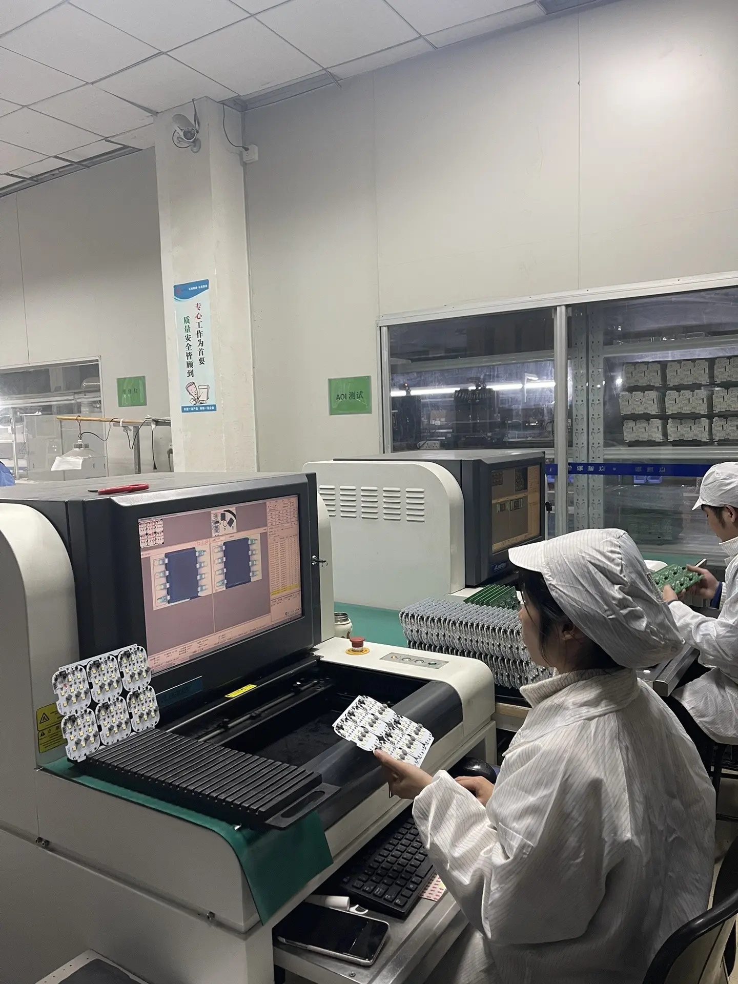
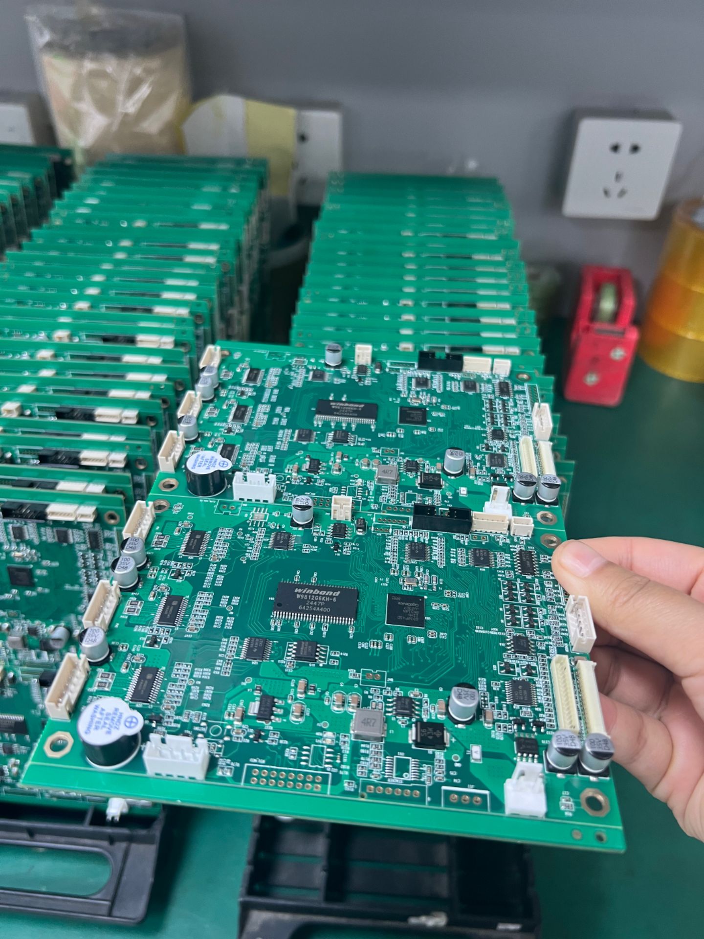
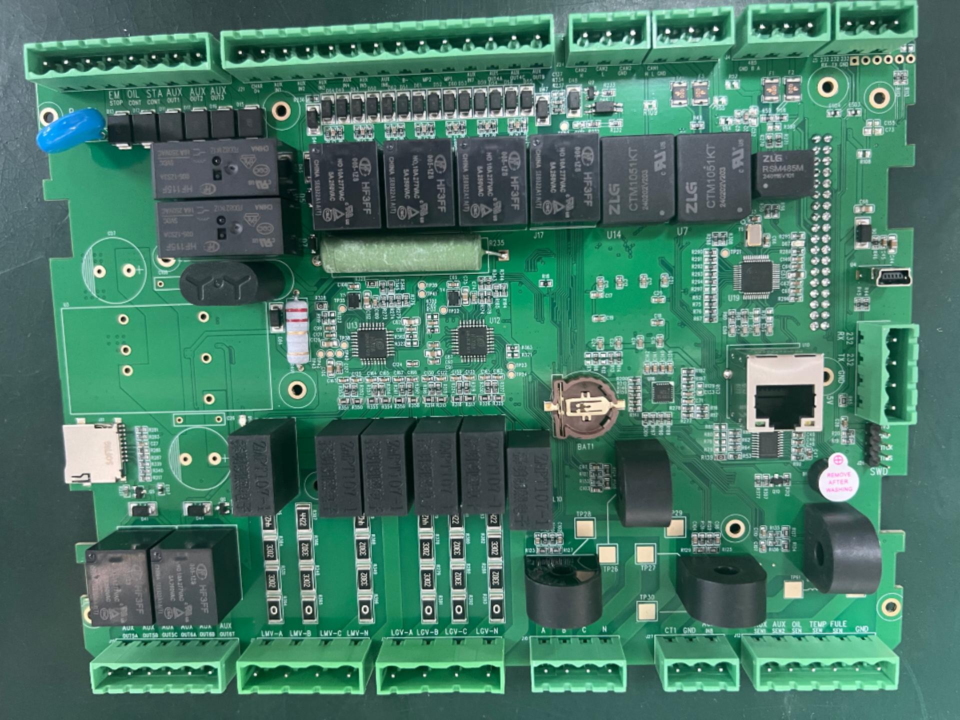
Can PCB traces have right-angle bends? Many PCB design guidebooks specifically point out that for critical high-speed signal lines, traces should not have 90-degree corners and must instead use two 135-degree angles. In PCB Layout software, this means selecting the 45-degree routing mode.
Why is there such a regulation? Do right angles have a negative impact on signal quality? The answer is yes. The width of the copper foil at the right-angle bend of a trace is wider than that of a straight trace, approximately 1.414 times the normal line width. This causes a sudden change in the characteristic impedance at the right-angle bend.
This does not cause problems for ordinary signal traces, but for high-speed transmission lines, changes in characteristic impedance can lead to signal reflection, deteriorating signal quality. At the same time, the additional parasitic capacitance at the corner can also cause delay effects on signal transmission.
In addition, the tip of the right angle is prone to emitting or receiving electromagnetic waves and can generate EMI.
In summary, it is recommended that right angles be prohibited in PCB layout, whether for ordinary signal lines, high-speed digital signal transmission lines, RF transmission lines, or copper cladding. All should be designed with obtuse angles.


10585 View